Steam is used extensively in the power industry to produce electricity. High pressure steam is used to turn a steam turbine at thousands of revolutions per minute, which is connected to an electrical generator. This electrical generator then generates electricity which is fed into an electrical grid. Typically these turbines would be on a coal, oil or nuclear power plants. However steam and steam turbines are playing an increasing important role in turning the sun’s rays into useable electricity.
Solar thermal technology is different from photovoltaic technology. Solar thermal electrical generation concentrates the light from the sun to create heat, which is then used to run a heat engine/turbine which turns a generator to make electricity. Solar thermal plants can easily incorporate heat storage during the day which converts the stored heat into electricity at night. Photovoltaic, or PV energy conversion directly converts the sun’s rays into electricity. This means that PV solar panels are only effective during daylight hours, because storing electricity is not a particularly efficient process.
To generate efficient electricity on a large scale the solar radiation from the sun needs to be concentrated, by using mirrors and lenses. Flat plate, non-concentrating type solar collectors are not suitable for efficient conversion to electricity. This is due to the fact that they will not reach temperatures much above 200 °C.
Commercial concentrating solar thermal power plants (CSP) were first developed in the 1980s. With the exception of the Shams solar power station, built in 2013 near Abu Dhabi in the United Arab Emirates, all other 100 MW or larger CSP plants are either located in the United States or in Spain.
Currently the world’s largest solar thermal power plant is the 392 MW Ivanpah plant, which was commissioned in 2014. The next biggest being the 354 MW SEGS installation. Both of these are located in the Mojave Desert of California in the USA.
| Operational Solar Thermal Power Stations | ||||
| MW | Name | Country | Location | Technology type |
| 392 | Ivanpah Solar Power Facility | USA | San Bernardino County, California | solar power tower |
| 354 | Solar Energy Generating Systems (SEGS) | USA | Mojave Desert, California | parabolic trough |
| 280 | Solana Generating Station | USA | Gila Bend, Arizona | parabolic trough |
| 250 | Genesis Solar Energy Project | USA | Blythe, California | parabolic trough |
| 200 | Solaben Solar Power Station | Spain | Logrosán | parabolic trough |
| 150 | Solnova Solar Power Station | Spain | Sanlúcar la Mayor | parabolic trough |
| 150 | Andasol solar power station | Spain | Guadix | parabolic trough |
| 150 | Extresol Solar Power Station | Spain | Torre de Miguel Sesmero | parabolic trough |
| 100 | Palma del Rio Solar Power Station | Spain | Palma del Río | parabolic trough |
| 100 | Manchasol Power Station | Spain | Alcázar de San Juan | parabolic trough |
| 100 | Valle Solar Power Station | Spain | San José del Valle | parabolic trough |
| 100 | Helioenergy Solar Power Station | Spain | Écija | parabolic trough |
| 100 | Aste Solar Power Station | Spain | Alcázar de San Juan | parabolic trough |
| 100 | Solacor Solar Power Station | Spain | El Carpio | parabolic trough |
| 100 | Helios Solar Power Station | Spain | Puerto Lápice | parabolic trough |
| 100 | Shams | UAE | Abu Dhabi Madinat Zayad | parabolic trough |
| 100 | Termosol Solar Power Station | Spain | Navalvillar de Pela | parabolic trough |
| 75 | Martin Next Generation Solar Energy Center | USA | Indiantown, Florida | ISCC with parabolic trough |
| 64 | Nevada Solar One | USA | Boulder City, Nevada | parabolic trough |
| 50 | Puertollano Solar Thermal Power Plant | Spain | Puertollano, Ciudad Real | parabolic trough |
| 50 | Alvarado I | Spain | Badajoz | parabolic trough |
| 50 | La Florida | Spain | Alvarado (Badajoz) | parabolic trough |
| 50 | Majadas de Tiétar | Spain | Caceres | parabolic trough |
| 50 | La Dehesa | Spain | La Garrovilla (Badajoz) | parabolic trough |
| 50 | Lebrija-1 | Spain | Lebrija | parabolic trough |
| 50 | Astexol 2 | Spain | Badajoz | parabolic trough |
| 50 | Morón | Spain | Morón de la Frontera | parabolic trough |
| 50 | La Africana | Spain | Posada | parabolic trough |
| 50 | Guzman | Spain | Palma del Río | parabolic trough |
| 50 | Olivenza 1 | Spain | Olivenza | parabolic trough |
| 50 | Orellana | Spain | Orellana la Vieja | parabolic trough |
| 50 | Godawari Green Energy Limited | India | Nokh | parabolic trough |
| 50 | Enerstar Villena Power Plant | Spain | Villena | parabolic trough |
| 31.4 | Puerto Errado | Spain | Murcia | fresnel reflector |
| 25 | Hassi R’Mel integrated solar combined cycle power station | Algeria | Hassi R’mel | ISCC with parabolic trough |
| 22.5 | Termosolar Borges | Spain | Borges Blanques | parabolic trough biomass hybrid |
| 20 | PS20 Solar Power Tower | Spain | Seville | solar power tower |
| 20 | Kuraymat Plant | Egypt | Kuraymat | ISCC with parabolic trough |
| 20 | Ain Beni Mathar Integrated Thermo Solar Combined Cycle Power Plant | Morocco | Ain Bni Mathar | ISCC with parabolic trough |
| 19.9 | Gemasolar | Spain | Fuentes de Andalucia (Seville) | solar power tower |
| 17 | Yazd Integrated Solar Combined Cycle Power Station | Iran | Yazd | ISCC with parabolic trough |
| 11 | PS10 Solar Power Tower | Spain | Seville | solar power tower |
| 10 | Delingha Solar Power Plant | China | Delingha | solar power tower |
| 5 | Greenway CSP Mersin Solar Tower Plant | Turkey | Mersin, Turkey | solar power tower |
| 5 | Kimberlina Solar Thermal Energy Plant | USA | Bakersfield, California | fresnel reflector |
| 5 | Sierra SunTower | USA | Lancaster, California | solar power tower |
| 5 | Archimede Solar Power Plant | Italy | Syracuse, Sicily | ISCC with parabolic trough |
| 5 | Thai Solar Energy (TSE) 1 | Thailand | Huaykrachao | parabolic trough |
| 9 | Liddell Power Station Solar Steam Generator | Australia | New South Wales | ISCC with fresnel reflector |
| 2.5 | Acme Solar Thermal Tower | India | solar power tower | |
| 2 | Keahole Solar Power | USA | Hawaii | parabolic trough |
| 1.5 | Jülich Solar Tower | Germany | Jülich | solar power tower |
| 1.5 | Beijing Badaling Solar Tower | China | Beijing | solar power tower |
| 1 | Feranova CSP Plant | Turkey | Aydin, Turkey | fresnel reflector |
| 1 | Saguaro Solar Power Station | USA | Red Rock, Arizona | parabolic trough |
| 1 | Yanqing Solar Power Station | China | Yanqing County | solar power tower |
| 0.5 | Shiraz solar power plant | Iran | Shiraz | parabolic trough |
| 0.25 | Augustin Fresnel Solar Power Station | France | Targassonne | fresnel reflector |
| 3650.8 | Overall operational capacity |
A common misconception with solar power is that it only generates power during daylight hours. While this may be true with other solar technologies, this is does not need to be the case with CSP thanks to thermal storage. In this way, the CSP plant can produce electricity day and night. If the CSP site has predictable solar radiation, then the CSP plant becomes a reliable power plant. Reliability can be even further improved by installing a back-up combustion system if deemed necessary. Other designs integrate a combined cycle power plant with a solar plant, this is called an integrated solar combined cycle power plant (ISCC).
There are different designs of solar concentrated power plants. However they all share the same principal of needing to track the sun in order to be able to concentrate the radiation. During the day the sun has different positions. For low concentration and low temperature systems tracking can be avoided (or limited to a few positions per year). For higher concentrations system the mirrors or lenses need to move and follow the position of the sun.
An easy way to split the types is to make a distinction is made between linear and dish concentrator systems. Within liner concentrator systems are different sub configurations.
Linear concentrator designs
Parabolic trough type plants
These types of plants use mirrors which move in a single axis. The mirrors are curved in shape like a trough and reflect the direct solar radiation onto an evacuated receiver (also called an, absorber or collector) featuring a coated stainless steel tube inside a glass envelope. This tube which runs the length of the trough, is positioned at the focal point of the reflectors. Within the steel tube a thermal fluid is circulated.
For changes in the position of the sun perpendicular to the receiver, the trough tilts east to west so that the direct radiation remains focused on the receiver. Seasonal changes in the angle of sunlight parallel to the trough does not require adjustment of the mirrors, since the light is simply concentrated elsewhere on the receiver.
The thermal fluid circulated within the steel tube receiver becomes very hot due to the solar radiation. Fluids can include synthetic oil, molten salt, or water for direct steam generation. In the most typical systems, thermo oil flows through the absorber tube.
The hot oil is pumped through a steam generator that creates steam at an approximate temperature of 390 °C, which runs a conventional steam turbine cycle to convert heat into electrical power. A share of the hot oil flow may be sent to a separate heat exchanger where molten salt is heated up. The heat in the molten salt can then be released back to the oil and then to the steam cycle during cloudy or night operational periods.
The parabolic trough collectors are built up in parallel to form a 300–600 metre long collector row, and a multitude of parallel rows form the solar collector field.
Since 1985 a solar thermal system using this principle has been in full operation in California in the United States. It is called the Solar Energy Generating Systems (SEGS) system. Other CSP designs lack this kind of long experience and therefore it can currently be said that the parabolic trough design is the most thoroughly proven CSP technology. The downside is that their concentration ration remains below 100 suns, which only allows temperatures up to a medium level (maximum of about 550 °C).
The SEGS is a collection of nine plants with a total capacity of 354 MW and had been the world’s largest solar power plant, both thermal and non-thermal, for many years. Nevada Solar One plant with a capacity of 64 MW is a newer plant
The 150 MW Andasol solar power stations are in Spain with each site having a capacity of 50 MW. Note however, that those plants have heat storage which requires a larger field of solar collectors relative to the size of the steam turbine-generator to store heat and send heat to the steam turbine at the same time.
The 280MW Solana Generating Station came online in Arizona in 2013 with 6 hours of power storage. Hassi R’Mel integrated solar combined cycle power station in Algeria and Martin Next Generation Solar Energy Center both use parabolic troughs in a combined cycle with natural gas
The collector field can also be formed from very long rows of parallel Fresnel collectors. In the focal line of these is a metal absorber tube, which is usually embedded in an evacuated glass tube that reduces heat losses. A special high-temperature, resistive selective coating additionally reduces radiation heat losses.
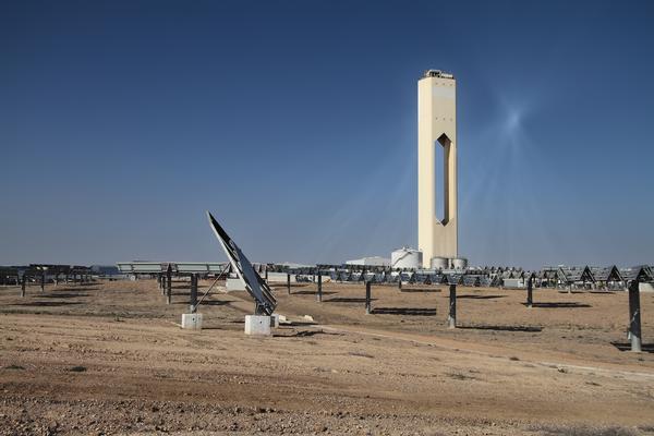
Solar power tower
These types of plant capture and focus the sun’s thermal energy with thousands of tracking mirrors (called heliostats) in roughly a two square mile field. A tower resides in the centre of the heliostat field. The dual-axis control heliostats focus concentrated sunlight on a receiver which sits on top of the tower.
The system must be very precise, to ensure that sunlight is really focused on the top of the tower. It is here that the absorber is located, and this is heated up to temperatures of 1000°C or more. This is due to the power tower design allowing for high level of concentration (1500 suns), which gives the high temperatures.
The first commercial tower power plant was PS10 in Spain with a capacity of 11 MW, completed in 2007. Ivanpah Solar Power Facility in California generates 392 MW of electricity from three towers, making it the largest solar power tower plant to date.
The heat in the power tower can used in various ways depending what it is absorbed by. Ultimately all four ways use a steam turbine in some form. These four ways can be defined below:
· Direct steam cycle
· Molten salt cycle
· Atmospheric air cycles
· Pressurised air cycles
Direct steam and molten salt cycles are in use at industrial and commercial scale, while the air cycles are at more experimental stage.
The direct steam cycle uses the heat directed at power tower to heat water which is evaporated in a cavity tube receiver. The generated steam is used to turn a condensing steam turbine. The steam is condensed and turned into water which is pumped back to the tower again. A steam storage vessel can be used for storage of steam.
Using molten salts as the primary heat absorber in the power tower allows for longer heat storage. Cold molten salt is pumped up the tower where it absorbs the heat. The hot salt then circulates through a steam generator to run a conventional steam cycle including a steam turbine. A hot storage tank between the tower and the steam generator allows the storage of a large amount of heat. This can be as much at 15 hours of heat storage, allowing for 24 plant operation. There are many interesting developments in salts which have wider liquid temperature ranges, enabling them to generate supercritical steam.
Atmospheric air cycles are based on an open loop where a blower transports ambient air through the receiver at the top of the tower, which is heated up by the reflected sunlight. The receiver consists of wire mesh or ceramic or metallic materials in a honeycomb structure, and air is drawn through this and heated up to temperatures between 650°C and 850°C. On the front side, cold, incoming air cools down the receiver surface. Therefore, the volumetric structure produces the highest temperatures inside the receiver material, reducing the heat radiation losses on the receiver surface. The air is either directed through a packed bed storage unit typically made of rocks (to provide heat storage), or through a steam generator driving a conventional steam cycle. A duct burner can also be used to help guarantee capacity with this type of solar thermal power plant. The return air from the steam generator is blown back to the receiver to start the process again.
The pressurised air cycle offers totally new opportunities for solar thermal tower plants. A compressor pressurizes air to about 15 bar; a transparent glass dome covers the receiver and separates the absorber from the environment. Inside the pressurized receiver, the air is heated to temperatures of up to 1100°C, and the hot air drives a gas turbine. This turbine is connected to the compressor and a generator that produces electricity. The waste heat of the gas turbine goes to a heat recovery steam generator type boiler which generates steam to drive a steam turbine. The combined gas and steam turbine process can reach efficiencies of over 50%, whereas the efficiency of a simple steam turbine cycle is only 35%. Therefore, solar system efficiencies of over 20% are possible.
Dish concentrating designs
Known as a dish Stirling system, it uses a large, reflective, parabolic dish (similar in shape to satellite television dish). It focuses all the sunlight that strikes the dish up onto a single point above the dish, where a receiver captures the heat. Typically the dish is coupled with a Stirling engine hence the name, Dish-Stirling System. A Stirling engine is a type of heat engine that is used in this case to turn an electrical generator.
Each dish generally develops about 3-25 kw, and they can be grouped together.
Conclusions
Concentrated solar power is proven and generating real power for users and industry. When looking at the amount of power generated by using CSP on a global basis it is clear that it is at the early stage of its development when compared with other renewable technologies such as photovoltaic panels or wind turbines. However unlike photovoltaic facilities, CSP plants have the potential in the long run to provide baseload capacity to the grid, and thus work together with other renewable energy technology that provides only peak load. The use of the power tower and the heliostat field provides the highest temperatures which lead to the best efficiencies. This is shown by a cost/performance comparison of power tower and parabolic trough concentrators made by the NREL which estimated that by 2020 electricity could be produced from power towers for 5.47 ¢/kWh and for 6.21 ¢/kWh from parabolic troughs. There is some hope that the development of cheap, durable, mass producible heliostat power plant components could bring this cost down.