There are good reasons to reduce steam pressure on a saturated steam system. This is done by using a pressure reducing valve. To ensure that this valve works correctly, can be maintained, and there is some form of safety back up, the valve will almost certainly form part of a station with other items. Therefore to reduce pressure we should think of a pressure reducing station and not just a valve on its own.
It is typical for steam to be generated at a higher pressure and for it to be used at a lower pressure. Therefore the pressure of the steam is reduced near the point of use by using a pressure reducing valve.
The reason for generating at high pressure and using at a lower pressure can be summarised below:
- Most steam boilers work better at higher pressures. This ensures that wet steam is not produced and steam is generated in the most economical way. Reducing the pressure of a boiler can typically lead to a reduction of its output.
- The maximum allowable working pressure (MAWP) of the item of steam equipment, is lower than the pressure of the steam boiler.
- Distributing steam at higher pressure has the advantage of using smaller steam mains. This is due to the volume required being smaller the higher the pressure.
- By accurately reducing the pressure, steam can be used to provide tight temperature control for items of equipment such as sterilisers. This is because the temperature of saturated steam is closely related to its pressure.
- By reducing steam to a lower pressure at the point of use will reduce the percentage of flash steam produced in the condensate system after the piece of steam using equipment. Reducing flash steam being produced will save energy, water and therefore cost.
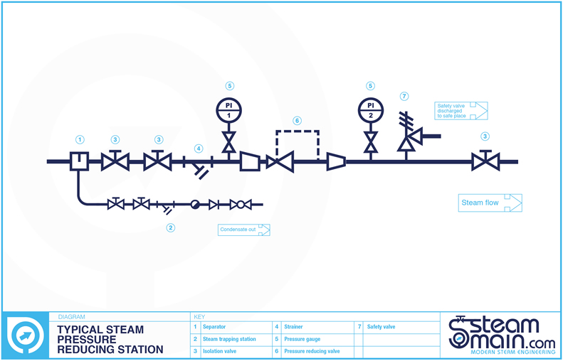
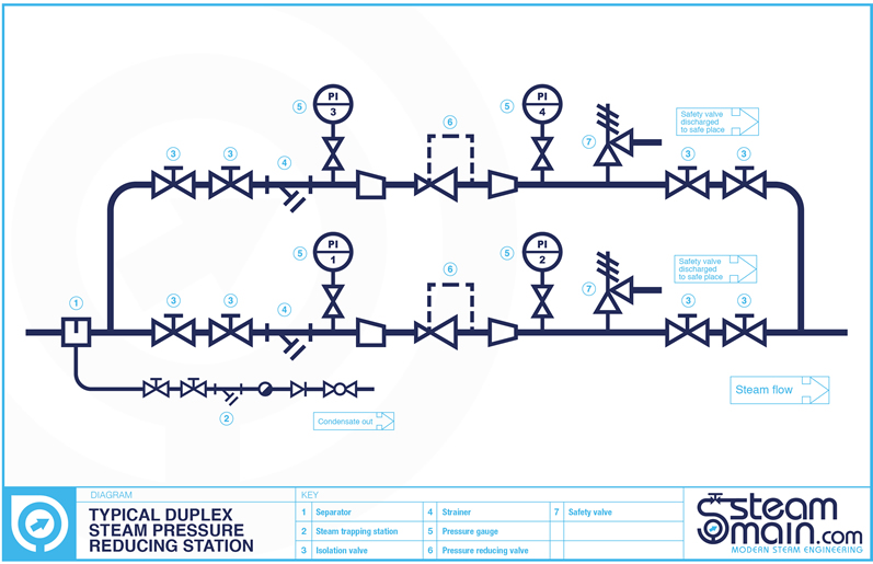
Steam pressure reducing stations may vary from but typically include separator and steam trap (or at least dirt pocket and steam trap), double upstream isolation, strainer, upstream pressure gauge, pressure reducing valve, downstream pressure gauge, safety valve, downstream steam trap (required depending on if PRV valve could experience dead end conditions and become water logged), downstream isolation. If the steam is serving a critical piece of plant or area, duplex pressure reducing stations are used. These are mounted in parallel and will probably use an extra downstream isolation valve to aid maintenance.

If the turndown of the steam required is beyond the scope of a single pressure reducing valve, two pressure reducing valves may be used in series. In practice this is not that common.
The role of each item in the station can be shown below:
- Separator and steam trap set. These remove any condensate at the bottom of the steam pipe and return it to the condensate return system. The separator contains baffles which turn the steam, causing any entrained moisture to be removed. This ensures that only dry steam is sent to the pressure reducing valve. When the isolation valves are closed down stream (perhaps when maintenance is performed on the pressure reducing valve), the separator and trap set will also continue to remove condensate. This allows maintenance to be safely performed without a wider site steam shut down.
- Double upstream isolation valves. These two valve provide safe isolation of the steam during any maintenance. A small bleed valve mounted at 90 degrees is sometimes installed in the pipework between the two valves. The pipe from this being routed to a safe place. The function of this valve is to check the standard of isolation of the first valve.
- Strainer with its perforated screen is used to make sure that any unwanted debris is removed from the steam before it reaches the pressure reducing valve itself.
- Upstream pressure gauge set is used so that the pressure being supplied to pressure reducing set can be measured.
- Pressure reducing valve itself, this will reduce the pressure of the steam supplied to what is required by the plant or process downstream. The valve should be sized and applied in accordance with the manufactures criteria. The valve should be able to control the downstream pressure to the accuracy that is required by the process or plant downstream. Manufacturers will normally have sizing charts, or electronic sizing programs to help select the correct valve.
- Downstream pressure gauge set is used so that the pressure being maintained by the pressure reducing set can be measured. This is vital for commissioning purposes when the pressure reducing valve is set up.
- Safety valve is present in the event of the pressure reducing valve failing. Plant and pipework downstream of the pressure reducing valve station will probably have a lower pressure rating than the steam pressure upstream. Therefore the safety valve ensures that if the pressure reducing valve fails open the downstream pressure does not rise above any downstream pressure ratings. Thought also has to be given to making sure that the safety valve will re-seat properly after any opening. Safety valve sizing is a subject on its own and we hope to cover in a later article. The exhaust from the safety valve should be piped to a safe place.
- Downstream isolation valve, is there so that the pressure reducing valve can be commissioned on a dead end condition. This involves closing the downstream isolation valve and adjusting the pressure reducing valve till it controls to the desired set point. This ensures that under different flow conditions the pressure reducing valve controls the downstream pressure to the set point required (within the design parameters of the pressure reducing valve). The downstream isolation valve will also be closed when maintenance is performed on the pressure reducing valve.
The pipework after the pressure reducing valve station should normally be larger than the pipework upstream. As the steam pressure is reduced, to ensure that the flow of steam is not restricted the volume needs to be increased, hence the increase in pipework diameter.
In conclusion when thinking of reducing stream pressure, think of the reducing station as a whole not just a valve on its own.