This article is a comprehensive explanation of steam traps and trapping and includes
- explanations of what they are,
- details of the relevant technical standards,
- describes the various types
- explains the importance of maintenance
What is a steam trap? Very simply it’s a valve that operates automatically to allow condensate, air or other gases to be discharged from a steam system, whilst also ensuring that steam stays ‘trapped’ in the steam system itself. A steam trap, and steam trapping is an essential part of a steam and condensate system.
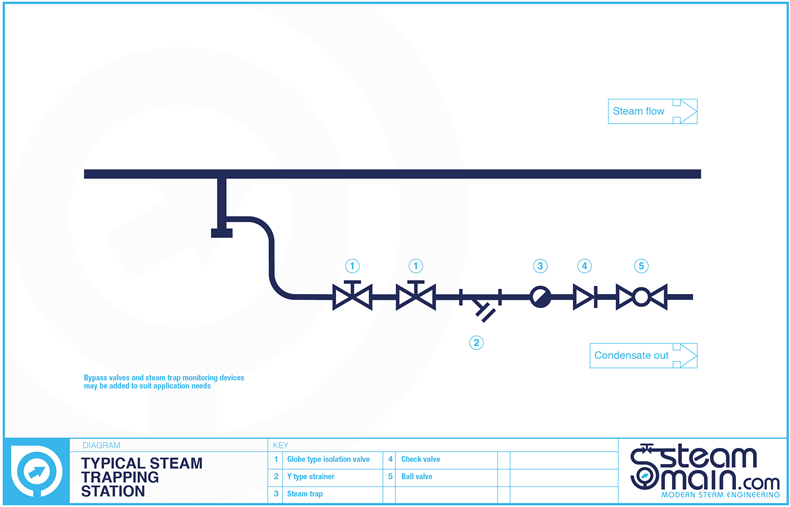
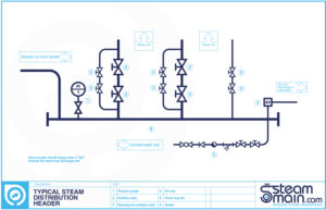
From the steam boiler a steam distribution system transports the steam to where it is required. It would typically consist of a steam header, steam distribution main, and steam off-takes from the main to the point of use. At places on these would be steam trapping stations.
Once steam has passed from the steam distribution system it moves to the steam consuming piece of plant. This could be to heat a medium by exchanging the heat in the steam by the condensing of the steam against a heat transfer surface, or to heat a medium by injecting the steam directly into it. It could be also be used to drive a mechanical piece of equipment like a steam turbine. The piece of steam consuming plant will typically have a control valve or similar to control the amount of steam used in it. Depending on the piece of equipment it will probably have a steam trap or similar to remove condensate as it forms but close and trap steam when no condensate is present.
Therefore the purpose of a steam trap is to trap steam and stop live steam escaping, however when condensate (condensed steam), air and other non-condensable gases are present (or formed) the steam trap must discharge these.
Steam traps operated in many different applications, pressures, temperatures, and locations. There is no way that one size or type of trap can be suitable for all of these. Therefore steam traps come in different types and sizes.
Different types of steam traps
There are many different types of steam traps, with so many steam trap manufacturers displaying a wide range of product information in many different formats it is easy to see why many purchasers and designers find the selection of steam traps confusing.
Below is a table containing the most important, national/international standards that apply to steam traps and are intended to ensure that any purchaser/designer has the full knowledge and confidence that the equipment used meets known legislation.
ISO 6552 : 1980 – Glossary of technical terms for automatic steam traps
This standard establishes precise definitions for all technical terms and expressions used to describe steam traps under operating conditions. Only by specifying these operating conditions can a customer be confident that the steam trap will safely operate within their system
| PN | Nominal pressure permissible | Working pressure which is dependent on materials, design and working temperatures/pressures. |
| PMA | Maximum allowable pressure (bar) | That the shell of the trap can withstand at a given temperature. |
| PMO | Maximum operating pressure (bar) | That which is given by the manufacturer, sometimes restricted by the pressure limitations of internal mechanisms. |
| PO | Operating pressure | Measured at the trap inlet (bar). |
| POB | Operating backpressure | Measured at the outlet of the trap (bar). |
| PMOB | Maximum operating backpressure (bar) | Maximum permissible pressure at the trap outlet allowing correct operation. |
| DP | Operating differential pressure (bar) | Difference between operating pressure and operating backpressure (bar). |
| DPMX | Maximum differential pressure (bar) | Maximum difference between operating pressure and operating backpressure. |
| DPMN | Minimum differential pressure (bar) | Minimum difference between operating pressure and operating backpressure. |
| PT | Test pressure (bar) | Pressure applied to the steam trap under test. |
| PTMX | Maximum test pressure (bar) | Maximum cold hydraulic test pressure the trap can withstand, with internals fitted. |
| TMA | Maximum allowable temperature (oC) | Maximum temperature to which the shell of the trap can be raised permanently, at a given pressure. |
| TMO | Maximum operating temperature (oC) | Maximum temperature for which the operation of the trap is guaranteed. |
| TO | Operating temperature (oC) | Temperature measured at the inlet of the trap being tested |
EN 26553 : 1991 ISO 6553 : 1980 – Marking of automatic steam traps
This standard establishes certain minimum basic requirements for the marking and identification of steam traps. To conform to this standard all traps should be marked with the following:
- Manufacturer’s name and/or trade mark
- Maximum allowable pressure (PMA)
- Maximum allowable temperature (TMA)
- Indication of the flow direction
Optional markings to include:
- Nominal pressure (PN)
- Maximum operating pressure (PMO) or maximum differential pressure (DPMX)
- Shell material designation
- Nominal size (DN)
- Maximum test pressure (PTMX)
If steam traps do not have this information clearly marked on them many insurance companies may not validate or insure the steam system
EN 26554 : 1991 ISO 6554 : 1980 – Face-to-face dimensions for flanged automatic steam traps
This standard specifies face-to-face dimensions for steam traps in the size range DN15 to DN50, for pressures up to PN40. It is mainly used in European influenced markets. There are 6 series of dimensions with the most commonly used being Series 1.
The following face-to-face dimensions are specified for Series 1 steam traps:
DN15: 150 mm
DN20: 150 mm
DN25: 160 mm
DN32: 230 mm
DN40: 230 mm
DN50: 230 mm
Note: There is currently no ASTM / ASME equivalent for steam traps
EN 27841 : 1991 ISO 7841 : 1988 – Determination of steam loss of automatic steam traps
This specifies two alternative test methods to determine the steam loss of automatic steam traps. Steam trap buyers can now make comparisons of true steam trap losses through various types of steam traps with the assurance that the figures published are accurate and all tests are conducted in accordance with this standard.
It is important to understand that under normal conditions steam traps do not waste steam. Wastage can only occur if there is no load (not practical even in a superheated system) or if the internals have been damaged.
EN 27842 : 1991 ISO 7842 : 1988 – Determination of discharge capacity of automatic steam traps
Like EN 27841and ISO 7841, this specifies two alternative test methods for use by manufacturers in order to determine discharge capacity for steam traps. A manufacturer’s compliance with this standard will put an end to difficulties experienced in the past over trap selection. The customer will no longer have to ask whether the capacity curves produced for any particular manufacturer of steam trap are based upon cold water or hot water condensate tests. Some manufacturers will include the capacity of internal air vents in the overall capacity of their float traps – the air vent is only open when condensate has sub-cooled
EN 26948: 1991 ISO 6948 : 1981 – Production and performance characteristic tests for automatic steam traps
This standard specifies tests which are used to ensure that the steam trap functions correctly and that the performance is acceptable for the design. The tests include product inspection, hydrostatic and operational checks.
ISO 6704: 1982
This standard classifies steam traps into three basic types from which all other variations will be classified, these classification types are:
Thermostatic
- These are traps that are operated by changes in fluid temperature.
- These traps respond to changes in temperature between saturated steam whose temperature is dependent on pressure and the temperature of condensate whose temperature is derived from the heat loss in the system, As heat loss increases, the temperature of the condensate will fall allowing the trap to open, thus passing the condensate at this lower temperature until steam replaces the loss and increases the temperature again which closes the trap.
- This group includes bimetallic and bellow type traps.
Mechanical
- These are traps that are operated by changes in fluid density.
- Mechanical traps employ either an open or closed float to actuate a valve that senses the difference in density between steam and condensate.
- This group includes ball float traps and inverted bucket traps.
Thermodynamic
- These are traps that are operated by changes in fluid dynamics.
- These traps operate by acting as phase detectors in that they can distinguish between liquid and gases, however, they are unable to separate steam and air or for that matter any other non-condensing gas and steam.
- This group includes thermodynamic, disc, impulse and labyrinth steam traps.
Selecting a steam trap
By now you would have realised that selecting the proper steam trap is important in the effective operation of steam systems. As referred too earlier, steam traps are automatic valves that open to pass condensate and close to prevent the flow of steam.
The functions of a steam trap in a steam system are to:
- Vent air from the system so steam can enter.
- Hold steam in the system until the steam latent heat is removed.
- Drain condensate from the system as it is formed after the latent heat is removed.
Removing condensate from piping helps prevent erosion and water hammer. Removing condensate from heat exchangers is required to make room for new steam for the heating process
Let’s consider the following steam traps:
- Float type steam trap
- Inverted bucket type steam trap
- Thermodynamic type steam trap
- Balance pressure type thermostatic steam trap
- Bimetallic type steam trap
- Venturi orifice type steam traps
Several types of traps may be used for a specific application. Factors to consider in selecting the type of trap include:
- Constant or modulating condensate load
- Constant or fluctuating pressure
- Speed of air venting required
- Trap location
Trap sizing
- Determine the maximum condensate load (capacity) requirement for the trap by referring to the manufacturers’ specifications for the system equipment.
- Determine the available steam inlet pressure at the trap (This pressure could be different than supply pressure at boiler).
- Determine the outlet pressure (backpressure) at the trap discharge. (Pressure against the outlet can be due to static pressure in return line or due to lifting to an overhead return).
- Determine the pressure differential across the trap. (inlet pressure – outlet pressure = differential pressure).
- Determine a Safety Factor. The Safety factor will depend on accuracy in determining condensate load, inlet and outlet pressures. Recommendations: Float & thermostatic trap 1.5 to 2.5, bucket trap 2 to 4, thermostatic trap 2 to 4, thermodynamic trap 1 to 1.2.
- Multiply normal maximum condensate load (as determined above) by safety factor.
- Use a capacity table, supplied by the manufacturer for the selected type of trap to determine the trap model number.
- Use ordering information charts, again supplied by the manufacturer to determine the part number.
Guidelines:
- The trap seat rating must always be higher than the maximum inlet pressure at the trap.
- When a modulating control valve controls the inlet to equipment, select a trap size with a pressure rating greater than the maximum inlet pressure at the trap.
- Trap capacity should be checked at the minimum differential pressure to assure complete condensate removal under all possible conditions.
Steam trap types, advantages and disadvantages

Float type
Operation
- On start-up, low system pressure forces air out through the thermostatic air vent. A high condensate load normally follows air venting and lifts the float, which opens the main valve.
- The remaining air continues to discharge through the open vent
- When steam reaches the trap, the thermostatic air vent closes in response to higher temperature, and the main float drops, which closes the main valve.
- Certain models can be supplied with a steam lock release (SLR) which provides an adjustable steam bleed. An SLR should be specified whenever the piping arrangement may permit the formation of a steam pocket which can prevent condensate from reaching the trap. In the past, the thermostatic air vent was a point of weakness if waterhammer was present in the system. Even the ball could be damaged if the waterhammer was severe. However, in modern float traps the air vent is a compact, very robust, all stainless steel capsule, and the modern welding techniques used on the ball makes the complete float-thermostatic steam trap very robust and reliable in waterhammer situations.
In many ways the float-thermostatic trap is the closest to an ideal steam trap. It will discharge condensate as soon as it is formed, regardless of changes in steam pressure.
Advantages of the float steam trap
- The trap continuously discharges condensate at steam temperature. This makes it the first choice for applications where the rate of heat transfer is high for the area of heating surface available.
- It is able to handle heavy or light condensate loads equally well and is not affected by wide and sudden fluctuations of pressure or flowrate.
- As long as an automatic air vent is fitted, the trap is able to discharge air freely.
- It has a large capacity for its size.
- The versions which have a steam lock release valve are the only type of trap entirely suitable for use where steam locking can occur.
- Is resistant to waterhammer.
Disadvantages of the float steam trap
- Although less susceptible than the inverted bucket trap, the float type trap can be damaged by severe freezing.
- As with all mechanical type traps, different internals are required to allow operation over varying pressure ranges.
Inverted bucket type steam trap
Operation
- As condensate reaches the trap, it forms a water seal inside the body. The weight of the bucket keeps the valve off its seat so condensate can flow around the bottom of the bucket and out of the trap. Under low load or superheat conditions, the trap may need to be “primed” with water before system start-up.
- When steam enters the underside of the bucket, the bucket becomes buoyant and rises. This positions the lever mechanism such that the main valve “snaps” shut.
- The bucket will lose its buoyancy as the enclosed steam condenses due to radiation losses, and steam escapes through the vent hole. Once this happens, the weight of the bucket will pull the valve off its seat and the cycle is then repeated. Any air reaching the trap will also give the bucket buoyancy and close the valve, preventing condensate flow. A small vent hole in the bucket will bleed air into the top of the trap. The vent hole is of small diameter to reduce steam loss and thus will vent air very slowly. Under start-up conditions, this is further compounded by the low differential pressures present. This can lead to waterlogging of the plant and subsequent poor heat transfer. A separate external air vent is normally required to ensure speedy and efficient start-up of a steam plant. A bimetal air vent assist can be added to some models to help with cold start-up air.
Advantages of the inverted bucket steam trap
- The inverted bucket steam trap can be made to withstand high pressures.
- Like a float-thermostatic steam trap, it has a good tolerance to waterhammer conditions.
- Can be used on superheated steam lines with the addition of a check valve on the inlet.
- Failure mode is usually open, so it’s safer on those applications that require this feature, for example turbine drains.
Disadvantages of the inverted bucket steam trap
- The small size of the hole in the top of the bucket means that this type of trap can only discharge air very slowly. The hole cannot be enlarged, as steam would pass through too quickly during normal operation.
- There should always be enough water in the trap body to act as a seal around the lip of the bucket. If the trap loses this water seal, steam can be wasted through the outlet valve. This can often happen on applications where there is a sudden drop in steam pressure, causing some of the condensate in the trap body to ‘flash’ into steam. The bucket loses its buoyancy and sinks, allowing live steam to pass through the trap orifice. Only if sufficient condensate reaches the trap will the water seal form again, and prevent steam wastage.
- If an inverted bucket trap is used on an application where pressure fluctuation of the plant can be expected, a check valve should be fitted on the inlet line in front of the trap. Steam and water are free to flow in the direction indicated, while reverse flow is impossible as the check valve would be forced onto its seat.
- The higher temperature of superheated steam is likely to cause an inverted bucket trap to lose its water seal. A check valve in front of the trap should be regarded as essential under such conditions. Some inverted bucket traps are manufactured with an integral check valve as standard.
- The inverted bucket trap is likely to suffer damage from freezing if installed in an exposed position with sub-zero ambient conditions. As with other types of mechanical traps, suitable lagging can overcome this problem if conditions are not too severe. If ambient conditions well below zero are to be expected, then it may be prudent to consider a more robust type of trap to do the job. In the case of mains drainage, a thermodynamic trap would be the first choice.
Thermodynamic type steam trap
Operation
- As inlet pressure to the trap increases, the disc lifts off the seat and allows the unwanted condensate to escape through the peripheral outlet surrounding the inlet
- As hot condensate reaches the disc chamber, it creates flash steam in the chamber. This flash steam travels at high velocity from the inlet to the outlets, creating a low pressure area under the disc. Some of the flash steam bypasses the disc and enters the top of the chamber, creating a build-up of pressure above the disc. This differential pressure causes the disc to close against the seat, trapping the steam.
- The flash steam above the disc is the only force opposing the pressure from the inlet condensate, keeping the valve closed. As heat transfer takes place in the upper chamber, the flash steam condenses and the pressure above the disc reduces. When the pressure above the disc falls to a point that is less than the pressure of the incoming condensate, the disc will lift again and repeat the cycle. Cycle time is dependent on steam temperature, and more importantly, ambient temperature outside the trap.
- Since the amount of time the valve is closed is primarily dependent on the heat transfer from the flash steam to the ambient environment, frequent cycling of the valve can occur in cold or wet environments. Applying an insulating cap over the cover of the trap will reduce the cycle rate.
Advantages of the thermodynamic steam trap
- Thermodynamic traps can operate across their entire working range without any adjustment or change of internals.
- They are compact, simple, lightweight and have a large condensate capacity for their size.
- Thermodynamic traps can be used on high pressure and superheated steam and are not affected by waterhammer or vibration.
- Thermodynamic traps are not damaged by freezing and are unlikely to freeze if installed with the disc in a vertical plane and discharging freely to atmosphere. However, operation in this position may result in wear of the disc edge.
- As the disc is the only moving part, maintenance can easily be carried out without removing the trap from the line.
- The audible ‘click’ which occurs as the trap opens and closes makes trap testing very straight forward.
Disadvantages of the thermodynamic steam trap
- Thermodynamic steam traps will not work positively on very low differential pressures, as the velocity of flow across the underside of the disc is insufficient for lower pressure to occur. They are subjected to a minimum inlet pressure (typically 0.25 bar g) but can withstand a maximum backpressure of 80% of the inlet pressure.
- Thermodynamic traps can discharge a large amount of air on ‘start-up’ if the inlet pressure builds up slowly. However, rapid pressure build-up will cause high velocity air to shut the trap in the same way as steam, and it will ‘air-bind’. In this case a separate thermostatic air vent can be fitted in parallel with the trap.
- Modern thermodynamic steam traps can have an inbuilt anti-air-binding disc which prevents air pressure building up on top of the disc and allows air to escape.
- The discharge of the trap can be noisy and this factor may prohibit the use of a thermodynamic trap in some locations, e.g. outside a hospital ward or operating theatre. If this is a problem, it can easily be fitted with a diffuser which considerably reduces the discharge noise.
- Care should be taken not to oversize a thermodynamic trap as this can increase cycle times and induce wear.
- Mains drainage applications often only need to be fitted with low capacity versions, providing proper consideration is given to siting the drain pockets correctly.
Balance pressure type thermostatic steam trap
Operation
- The operating element is a capsule containing a small quantity of a special liquid with a boiling point below that of water, this liquid’s actions are similar in nature to that of a refrigerant. In the cold conditions that exist at start-up, the capsule is relaxed.
- The valve is off its seat and is wide open, allowing unrestricted removal of air. This is a feature of all balanced pressure traps and explains why they are well suited to air venting.
- As condensate passes through the balanced pressure steam trap, heat is transferred to the liquid in the capsule. The fill liquid boils before steam reaches the trap. The vapour pressure within the capsule causes it to expand and the trap shuts.
- Heat loss from the trap then cools the water surrounding the capsule, the fill condenses and the capsule contracts, opening the valve and releasing condensate until steam temperature approaches again at which the cycle is repeated.
Advantages of the balanced pressure steam trap
- Small, light and has a large capacity for its size.
- The valve is fully open on start-up, allowing air and other non-condensable gases to be discharged freely and giving maximum condensate removal when the load is greatest.
- This type of trap is unlikely to freeze when working in an exposed position (unless there is a rise in the condensate pipe after the trap, which would allow water to run back and flood the trap when the steam is off).
- The modern balanced pressure trap automatically adjusts itself to variations of steam pressure up to its maximum operating pressure.
- Trap maintenance is simple. The capsule and valve seat are easily removed, and replacements can be fitted in a few minutes without removing the trap from the line.
Disadvantages of the balanced pressure steam trap:
- The older style balanced pressure steam traps had bellows which were susceptible to damage by waterhammer or corrosive condensate. Welded stainless steel capsules introduced more recently, are better able to tolerate such conditions.
- In common with all other thermostatic traps, the balanced pressure type does not open until the condensate temperature has dropped below steam temperature (the exact temperature difference being determined by the fluid used to fill the element). This is clearly a disadvantage if the steam trap is chosen for an application in which waterlogging of the steam space cannot be tolerated, for example; mains drainage, heat exchangers, or critical tracing.
Bimetallic type steam trap
Operation
- On start-up, the bimetallic element is relaxed and the valve is open. Cooled condensate, plus air, is immediately discharged.
- Hot condensate flowing through the trap heats the bimetallic element causing it to pull the valve towards the seat. As the hot condensate is discharged and approaches steam saturation temperature the bimetallic element closes the valve.
- When there is no flow through the trap the condensate surrounding the element cools causing it to relax and the upstream pressure opens the valve. Condensate is discharged and the cycle repeats.
There are variations of this model that use a basic bimetal element in a slightly different way. One type uses three elements to provide additional force to open the main valve.
Another type uses the bimetal element as a pilot mechanism, such when condensate cools, the element opens and allows pressure to build up on top of the main piston. This pressure is used to open the main valve. As condensate temperature increases, the bimetal element will close and the piston pressure will fall allowing the main valve to be closed by the spring
Advantages of the bimetallic steam trap:
- Bimetallic steam traps are usually compact, yet can have a large condensate capacity.
- The valve is wide open when the steam trap is cold, giving good air venting capability and maximum condensate discharge capacity under ‘start-up’ conditions.
- As condensate tends to drain freely from the outlet, this type of steam trap will not freeze up when working in an exposed position.
- The bodies of some bimetallic steam traps are designed in such a way that they will not receive any damage even if freezing does occur.
- Bimetallic steam traps are usually able to withstand waterhammer, corrosive condensate, and high steam pressures.
- The bimetal elements can work over a wide range of steam pressures without any need for a change in the size of the valve orifice.
- If the valve is on the downstream side of the seat, it will tend to resist reverse flow through the steam trap. However, if there is any possibility of reverse flow, a separate check valve should be fitted downstream of the trap.
- As condensate is discharged at varying temperatures below saturation temperature and, provided waterlogging of the steam space can be tolerated, some of the enthalpy of saturated water can be transferred to the plant. This extracts the maximum energy from the condensate before it drains to waste, and explains why these traps are used on tracer lines where condensate is often dumped to waste.
- Maintenance of this type of steam trap presents few problems, as the internals can be replaced without removing the trap body from the line.
- The flash steam produced whenever condensate is discharged from a higher to a lower pressure will tend to cause an increase in backpressure in the condensate line.
- The cooling leg allows the condensate to cool down, producing less flash steam in the condensate line and thus helping to reduce the backpressure.
Disadvantages of the bimetallic steam trap:
- As condensate is discharged below steam temperature, waterlogging of the steam space will occur unless the steam trap is fitted at the end of a long cooling leg, typically 1 – 3 m of unlagged pipe.
- Bimetallic steam traps are not suitable for fitting to process plants where immediate condensate removal is vital for maximum output to be achieved. This is particularly relevant on temperature controlled plants.
- Some bimetallic steam traps are vulnerable to blockage from pipe dirt due to low internal flow velocities. However, some bimetallic traps have specially shaped valve trims that capture the discharge energy to open the valve more. These tend to give an intermittent blast discharge characteristic rather than a continual dribble discharge, and as such tend to be self-cleaning. These valve trims are sometimes referred to as dynamic clacks.
- If the bimetallic steam trap has to discharge against a significant backpressure, the condensate must cool to a lower temperature than is normally required before the valve will open. A 50% backpressure may cause up to a 50°C drop in discharge temperature. It may be necessary to increase the length of cooling leg to meet this condition.
- Bimetallic steam traps do not respond quickly to changes in load or pressure because the element is slow to react.
Venturi orifice type steam traps
Operation
The venturi orifice trap works by having a plate or simple orifice trap which has a limited operating range on varying loads. It will work if the loads are relatively constant e.g. distribution systems. The venturi orifice trap works by combing venturi technology with the orifice. The capacity of the venturi orifice trap is related to the size of the orifice and also to the backpressure generated inside the venturi. It is a combination of these two factors that gives the venturi orifice trap its overall capacity.
- As the condensate passes through the orifice there is a pressure loss. On the upstream side of the orifice (the heat exchanger or steam line side) the condensate has the same pressure and temperature as the steam and therefore contains a lot of energy (it’s hot). As it drops pressure across the orifice, the temperature and pressure of the condensate reduces, resulting in it containing less energy. However, energy cannot disappear. So the difference in energy between the high pressure/temperature upstream side and the low pressure/temperature downstream side (i.e. the condensate return system) is converted into steam
- The higher the pressure difference across a trap the more condensate has to be converted into ‘flash’ steam. Venturi orifice technology uses this flash steam to create a backpressure inside the venturi.
- As the condensate is forced through the orifice of the steam trap by the upstream pressure, the resultant pressure drop generates flash steam. This flash steam is 1000 times the volume of the condensate, so the sudden expansion results in the condensate being accelerated in the venturi part of the trap. This sudden acceleration creates an opposite and equal force or backpressure inside the venturi, which acts to restrict the flow of condensate through the orifice.
- Because the amount of flash steam changes, depending upon the operating conditions, the resultant backpressure also changes. This then becomes a self-regulating flow of condensate through the trap that gives variable capacity characteristics.
.Advantages of venturi orifice steam traps
- Performance can be computed if the condensate load and inlet and outlet pressures are known.
- Continuous discharge.
- No moving parts.
- Easy to maintain.
- Cannot fail open, but erosion can gradually cause an increase in the orifice diameter.
- Resistant to damage by water hammer and thermal shock.
- Pressure drop across the orifice reduces potential for overpressure of the downstream condensate system.
- Resistant to freeze damage.
- Can be mounted in several positions.
Disadvantages of venturi orifice steam traps
- Usual failure mode is closed due to plugging or blockage by dirt or debris.
- Screen or strainer may be required to reduce possibility of plugging or blockage.
- Live steam losses are usually small when the orifice is properly sized, but wear and erosion can enlarge the orifice and cause excessive loss of live steam.
- Orifice opening cannot be adjusted to accommodate varying condensate loads.
- Automatic or manual drain valve may be required to accommodate large condensate loads that occur during start up or periods of high demand.
- Air can only be discharged very slowly during start up.
- Engineering is required to select the appropriate size orifice for a particular application (ineffective if oversized or undersized).
- Consequences of live steam in the return system must be evaluated.
- Difficult to field check because of continuous discharge.
- Does not function effectively when back pressure is excessively high.
- If the load is likely to vary by a factor of 2 or 3, the orifice plate steam trap may not be cost-effective because waterlogging or flooding is possible or excessive steam may escape.
Testing and maintenance of steam traps
Up to 20% of the steam that leaves a steam boiler can be lost in a plant via leaking steam traps. An example is a steam trap with a typical 3mm orifice under a pressure of 7 bar which results in the loss of approximately 25 tonnes of steam per annum.
There are several ways of checking that a steam trap is working correctly. This can even be incorporated as part of the steam trap station. However, typically, industry takes three broad approaches to test steam traps:
Visual inspection
Visual inspection depends on a release valve situated downstream of the steam trap. An inspector opens these valves and looks to see if the trap is discharging condensate or steam. This demands an in-depth understanding of the difference between flash steam and “live” steam, and can expose the technician to the potential and damaging release of hot steam. Therefore the release valve must discharge to a safe place. Though a relatively low-cost option, there is a small additional cost associated with installing online visual testing components. Another visual way is if the steam trap station has a sight glass mounted after the steam trap. Again the technician must an in-depth understanding of what they are looking for in the sight glass.
Thermal measurement
Thermal tests can be achieved with many different devices. Each has pros and cons. However while thermal measuring equipment is a vital weapon and must be an integral part of a steam system testing program, it cannot provide a definitive answer on a steam traps health. During infrared testing, the effect of the piping composition and/or insulation material on emissivity must be considered.
Acoustic/ultrasonic inspection
Acoustic techniques require the technician to listen to and detect steam trap operations and malfunction. This method includes various forms of listening devices such as doctors stethoscopes, screwdrivers, mechanical stethoscopes and ultrasonic detection instruments.
The ideal listening device allows the technician to listen to the sounds of steam trap operation while ignoring most ambient pipe sounds. This is where ultrasonic listening devices excel. Since they are sensitive to high frequency (short wave) signals, they tend to ignore most stray pipe signals. Also, they are very directional in their pick-up. For this reason, they will allow users to hear and see on meters the exact operations of steam traps.
Ultrasonic detectors usually have a stethoscope module, which contains an ultrasonic transducer attached to a metal rod that acts as a “wave guide”. The wave guide is touched on the downstream side of a trap to determine trap condition such as mechanical movements or steam and condensate flow. Most ultrasonic detectors amplify the high frequency signal (typically between 20-100 kHz) and translate them into the audible range where they are heard through headphones or seen as intensity increments on a meter. Some include frequency tuning to allow users to tune into desired trap sound.
The sensitivity of most high frequency monitoring equipment allows the testing person to hear not only completely failed steam traps (blowing steam), but even leaking steam from a trap in operation. Knowing what to look for and listen to is one of the challenges with this type of equipment, so the experience of the technician is therefore of paramount importance in the process.
Record keeping
Just as important as testing each steam trap itself is the recording of the testing results. As a general rule the following should be documented:
Documenting each trap station noting the following components: Isolation valves (inlet and outlet) inlet strainers, blowdown valves on the strainer, outlet check valves (if needed), trap station bypass, test valves or sight glass flow indicator.
Tag trap with its own numbered tag.
Document traps location, application, steam pressure, manufacturer, model type and trap size, and connection type.
Provide the result of each trap test itself; working correctly, leaking failed open, failed shut, plugged, not in service, etc.
From this documentation return on investment and energy saving calculations can be made. In some cases the return on investment may be less than one year.
A proactive steam trap management programme can have a huge impact on lowering energy costs. It can either be done by on-site personnel or contracted out to one of the many specialists that offer this type of service. Once the survey has been done, always ensure that any faulty steam traps do actually get changed or overhauled.