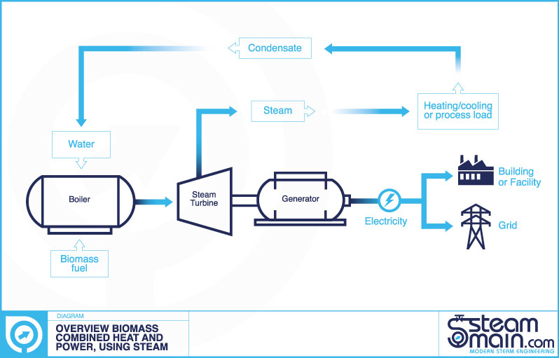
A steam and condensate system can be looked upon as a loop or cycle. There are several stages and pieces of equipment that make up this loop. Below is the overview of a typical loop or cycle.
Water supply and treatment; this is essential in allowing the steam to be produced for the steam and condensate cycle. Raw water is treated using a water treatment plant and program.
Boiler hotwell feedtank; is the place where the treated water is sent to. If condensate is returned from the process it is mixed with this treated cold make up water in a deaerator.
The Boiler; is the heart of a steam system. Without it steam could not be generated. The boiler is heated in many ways, such as burning fuels like gas, oil or coal, from burning waste, or from waste heat recovery from a variety of sources. The boiler turns water into steam. There are many different types and designs of boilers available.
Steam distribution system; transports the steam to where it is required. It would typically consist of a steam header, steam distribution main, and steam off-takes from the main to the point of use.
Steam consuming plant; uses steam as part of its process. This could be to heat a medium by exchanging the heat in the steam by the condensing of the steam against a heat transfer surface, or to heat a medium by injecting the steam directly into it. It could be also be used to drive a mechanical piece of equipment like a steam turbine.
Condensate return system; collects the condensate formed from the steam consuming equipment (and from any distribution areas) and returns it back the boiler hotwell feedtank.
Water treatment:
Steam is produced from water. It is therefore important for the water to be of the good enough quality so that; the steam produced is of the correct quality, and that the boiler, steam, and condensate systems functions correctly and do not break down or suffer harm.
All natural waters (including drinking water) contain different types and amounts of impurities. The natural water quality can vary from region to region, and country to country depending on its source and local minerals.
If we took a good quality drinking water and used it in a steam boiler it would cause problems and possible damage. Therefore it is important that water, we shall call it raw water is put through an appropriate treatment regime so that is becomes of a quality suitable for use in a steam boiler.
Raw water is normally supplied from a well or borehole, or from a towns water supply connection. The raw water is then treated using a water treatment plant and program.
This treatment will ensure that the boiler, steam and condensate system does not suffer from:
- Scale
- Corrosion and/or chemical attack
Raw water must be treated therefore to ensure that it becomes boiler feedwater quality. This is done by using a water treatment plant and a chemical program. For a simple shell boiler this may take the form of a base exchange softener plant. For a high pressure, high quality, power station water tube type boiler application, a demineralisation plant may be used.
Boiler hotwell feedtank:
The boiler hotwell feedtank is where water for the steam boiler is supplied from. The boiler hotwell feedtank is used to store this water ready for when the boiler requires it to produce steam. It is important that it is sized and designed correctly. The stored water in the feedtank is a mainly mixture of make-up water from the water treatment plant, condensate return coming back from the steam using process, and steam injected into the tank to keep the tank at its operating temperature.
The feedtank is kept hot (hence the name hotwell), but why is this required? It is kept hot to:
- Minimise the oxygen and other gases contained in the feedtwater: If water in the feedtank is kept at a high enough temperature the amount of dissolved oxygen and other gases is reduced. This means that less chemicals (sodium sulphite) are required in the feedwater. This saves chemicals and cost. In addition it reduces blowdown required in the boiler.
- To make sure that the boiler is not damaged: If cold water was sent to the boiler then thermal shock could be the result in the boiler. This cold water could introduce thermal shock to the hot surfaces in the boiler (boiler tubes and walls).Therefore hotter feedwater being sent to the boiler will reduce this risk.
- To make sure the boiler performs as rated: If cold water is supplied to the boiler the boiler has to work harder to generate steam at the desired pressure and temperature. This results in the output of steam that the boiler can actually produce being reduced. A shell boiler’s rated output (F&A rating) will normally be based on feedwater being at 100 °C.
Due to these three reasons the water in the atmospheric boiler hotwell feedtank is typical kept at more than 80 °C but less than 100 °C (pressurised deaerator feedwater tanks are typically kept at 105 °C)
It will of course require energy to keep the feedtank hot (normally through steam injection into the feedtank). However the water would still need to be heated in the boiler so the energy used in heating the water in the tank is not additional energy. The tank will have some standing energy losses (heat loss). However provided the tank is properly insulated this will be negligible, certainly in comparison to the advantages to having the water in the tank hot.
Feedtanks types can normally be broken down into two main types. They differ due to the type of deaerator used on the tank.
- Atmospheric boiler feedwater hotwell tank and atmospheric deaerator.
- Pressurised boiler feedwater hotwell tank and pressurised deaerator.
Atmospheric boiler feedwater hotwell tank: This type of tank is vented to atmosphere so is not under any system pressure. It the most common type of design used in steam systems. The tank can be rectangular or cylindrical (either vertical or horizontal).
Pressurised boiler feedwater hotwell tank and pressurised deaerator: This type of feedtank and deaerator combination is generally used on large plant or where the quality of the feedwater needs to be very high. Live steam is used to elevate the temperature above 100 °C to drive off oxygen. Live steam is used in the deaerator head and is injected into the cold make up feedwater and the condensate return. A blanket of steam is also maintained over the top of the water in the tank to prevent any further gas being re-absorbed into the feedwater. Pressurised deaerators typically work at about 0.2 barg. As this type of tank is pressurised it must be fitted with appropriate safety devices and inspected periodically.
Different types of steam boilers:
Steam is formed in a device generally called a boiler. Boilers can come in many different types and sizes. The shell type boiler is the most common type, and the type which we will use as our example throughout the rest of the boiler section of this article.
Shell type boilers are so called due to the heat transfer surfaces being contained within a steel shell. The product of the combustion from the burner flows through the tubes in the boiler and then out through the flue/chimney/stack. The water which is to be heated to form steam is contained in the vessel. The heat from the tubes flows into the water.
The most common type of shell boiler is the two or three pass type. The term “pass” is used to define the number of times the product of the burner goes through the sections of tubes to heat the water in the boiler. A two pass boiler would typically have efficiency in the region of 78%. While a three pass boiler would typically have an efficiency of about 87%.
Steam boiler fittings and accessories:
A boiler is more than just a shell and heat exchange surfaces. It needs many items on it to make sure that it functions safely in producing steam.
A fired boiler (as opposed to a waste heat boiler) requires a fuel to be combusted to make the boiler work. Therefore the boiler has a burner on it which the fuel is fed into. The fuel could be for example; oil, gas, or coal. It is the burner’s job to combust the fuel and adjust the amount of heat that it puts out. Therefore the burner will have a control system which adjusts it as required.
The product of the combustion will be exhausted from the boiler up the chimney, sometimes called a flue. The flue should be designed so that it can remove the gases from the boiler safely and handle the heat of these gases.
As the boiler shell is a pressure vessel it needs to have protection from over pressure and risk of subsequent explosion. This is done with the use of a safety valve.
To open and close the outlet of the boiler a boiler crown (or stop) valve is used. This would normally be of rising globe type with an indicator on it. The valve only being used in an open or closed position.
To generate steam there needs to be water in the boiler. With the boiler operating at pressure the water from the boiler feedwater hotwell is pumped into the boiler under pressure using a boiler feedwater pump. The pump must always be able to overcome the pressure in the boiler so that water can flow into the boiler.
To protect the boiler, and produce the correct quality of steam the water quality in the boiler must be maintained. Even when a good and correct water treatment plant and regime is used there will still be a requirement to blow impurities out of the boiler. This is done in two ways; using TDS blowdown, and bottom blowdown.
The total dissolved solids level in the boiler must be kept to a set level or set point. This is normally done using a side connection on the boiler, a TDS conductivity probe, and a control valve. The probe measures the TDS level in the water in the boiler and opens and closes the valve as desired to remove the TDS laden water from the boiler.
The second blowdown from the boiler is normally located at the bottom and back of the boiler. It is used to remove the sludge or sediment that accumulates at the bottom of the boiler shell. Therefore it is only opened for a short period of time (a few seconds), and normally only a few times a day at most. The valve can be opened manually using a key to operate the valve (a key is used so only one boiler can be blowdown at any one time, on multi boiler installations). Alternatively it can be automated using an air operated valve on a timer.
During operation it is important that the pressure and water level in the boiler can be seen. Therefore the boiler should have at least one pressure indicator (pressure gauge of correct standard), and a water level indicator.
The correct level of water in the boiler is essential to the safe and proper operation of the boiler. This is done by the water level controls on the boiler. These level controls provide the signal to the boiler feedpump or feedwater valve to make sure that water is fed into the boiler when required and shut off when not required. The water level controls on the boiler also provide alarms in case of low water level (and in some cases high level alarms).
To make sure that air is removed from the boiler, and to make sure that vacuum conditions are not present, it would be normal to incorporate a method of venting air from the boiler and a vacuum breaker.
Steam distribution:
A steam distribution system transports the steam to where it is required. It would typically consist of a steam header, steam distribution main, and steam off-takes from the main to the point of use. At places on these would typically be; steam trapping, steam metering, air venting, isolation valves, and pressure reducing stations.
A steam distribution system starts in the boiler house and the off take from the boiler(s) are normally sent to a manifold or header. The steam manifold or header will then have numerous take off points to send the steam where it is required. To keep pipe size and therefore cost down steam is generally produced at a higher pressure and reduced down in pressure at point of use.
Steam pipework is normally constructed from carbon steel. For more exotic high temperature and pressure steam mains higher specification alloys may be used.
Steam mains and pipework can be sized by velocity or pressure drop. Allowances should be made for adequate pipework support and expansion.
Branch lines off a steam main or steam line should always come off the top. This to ensure that dry steam is sent down the branch line. If the branch line came off the bottom condensate would may be sent down the branch line in addition to steam.
Air venting:
When a steam system is started from cold it will be full of air that needs to be removed. If air is not removed properly the warm up period will be extended, and efficiency is compromised. In addition small amounts of air and other non-condensable gases will enter a steam system during normal operation. It is important that these be removed also.
The best way to remove air from a saturated steam system is to use an automatic air vent. Automatic air vents should be fitted at high points at the end of steam main for example, or at the high point on equipment where air could be trapped. The discharge from these automatic air vents should always be piped to a safe place.
Steam trapping:
A steam trap, and steam trapping is an essential part of a steam and condensate system.
From the steam boiler a steam distribution system transports the steam to where it is required. It would typically consist of a steam header, steam distribution main, and steam off-takes from the main to the point of use. At places on these would be steam trapping stations.
Once steam has passed from the steam distribution system it moves to the steam consuming piece of plant. This could be to heat a medium by exchanging the heat in the steam by the condensing of the steam against a heat transfer surface, or to heat a medium by injecting the steam directly into it. It could be also be used to drive a mechanical piece of equipment like a steam turbine. The piece of steam consuming plant will typically have a control valve or similar to control the amount of steam used in it. Depending on the piece of equipment it will probably have a steam trap or similar to remove condensate as it forms but close and trap steam when no condensate is present.
Therefore the purpose of a steam trap is to trap steam and stop live steam escaping, however when condensate (condensed steam), air and other non-condensable gases are present (or formed) the steam trap must discharge these.
Steam traps operated in many different applications, pressures, temperatures, and locations. There is no way that one size or type of trap can be suitable for all of these. Therefore steam traps comes in different types and sizes.
These can be defined below:
- Thermostatic steam traps are ones which operate by a change in temperature. They open when they sense the lower temperature of the condensate and close when they come in contact with the higher temperature of the steam.
- Mechanical steam traps are ones which operate by the change of the mediums density. Condensate (water) will cause the mechanical device in the trap (float or bucket) to open the valve which allows the condensate to be removed from the trap. Steam being of lower density than condensate will cause the valve to close and shut so steam cannot flow.
- Thermodynamic steam traps are one which rely on the formation of “flash” steam. The most typical type of steam trap in this group is the thermodynamic disc type trap. The disc in the trap shuts when flash steam leaks round onto the top of the disc. Condensate however lifts the disc and can flow away.
Depending on the application it would be normal for the steam trap to be installed with other equipment around it to make a steam trapping station. A steam trapping would typically consist of upstream isolation, strainer, steam trap monitor (if fitted), steam trap itself, sight glass (if fitted), check valve, downstream isolation.
Pressure reduction:
It is typical for steam to be generated at a higher pressure and for it to be used at a lower pressure. Therefore the pressure of the steam is reduced near the point of use by using a pressure reducing valve.
The reason for generating at high pressure and using at a lower pressure can be summarised below:
- Most steam boilers work better at higher pressures. This ensures that wet steam is not produced and steam is generated in the most economical way. Reducing the pressure of a boiler can typically lead to a reduction of its output.
- The maximum allowable working pressure (MAWP) of the item of steam equipment, is lower than the pressure of the steam boiler.
- Distributing steam at higher pressure has the advantage of using smaller steam mains. This is due to the volume required being smaller the higher the pressure.
- By accurately reducing the pressure, steam can be used to provide tight temperature control for items of equipment such as sterilisers. This is because the temperature of saturated steam is closely related to its pressure.
- By reducing steam to a lower pressure at the point of use will reduce the percentage of flash steam produced in the condensate system after the piece of steam using equipment. Reducing flash steam being produced will save energy, water and therefore cost.
It would be typical for pressure reducing valves to be accompanied by other equipment to form a pressure reducing station. This would typically include; a separator and steam trap, upstream isolation, strainer, upstream pressure gauge, pressure reducing valve, downstream pressure gauge, safety valve, downstream isolation.
The most common group of pressure reducing valves themselves can be divided into the following main groups:
- Direct operating self-acting pressure reducing valves.
- Pilot operated self-acting pressure reducing valves.
- Actuated globe type control valves (electric or pneumatic actuated).
Safety valves:
A type of valve which is used to protect equipment, property, and life. It should be used as a backup in case of failure of normal plant. It does this by preventing overpressure of a piece of equipment or plant by opening at a pre-determined set pressure and releasing a volume of medium through it to make sure that excess pressure does not result. It may be the only device left to prevent a major and possibly fatal failure. It is therefore essential that a safety valve is selected, installed, and maintained in such a manner that it can operate when required at all times and under all conditions.
Typically safety valves are installed on; boilers and other pressure vessels, and after a pressure reducing valve (in case the pressure reducing valve were to fail). They should be sized and installed so that they ensure that the maximum allowable working pressure (MAWP) of a system or vessel is not exceeded, were the primary control systems to fail.
Condensate recovery and flash steam:
Steam is generated and used to heat a medium or to drive a mechanical piece of equipment like a steam turbine. To heat a medium the steam gives up its energy by exchanging the heat contained in it by condensing against a heat transfer surface. The steam therefore changes state back to water (called condensate). This condensate formed from the steam consuming equipment (and from any distribution areas) should be returned back the boiler hotwell feedtank. Condensate is a very valuable part of the steam and condensate cycle, as condensate contains valuable heat, and treated water which can be re-used in the steam and condensate cycle again. Therefore it is very important to wherever possible return as much condensate as possible to the boiler hotwell feedtank. A typical condensate return system might consist of a condensate return header to collect the condensate back to a certain point, a condensate return pump (could be electric or steam powered), and a condensate return main to return back to the boiler hotwell feedtank.
When steam is condensed it turns into water (condensate), which is removed via steam traps to the condensate return system. When the condensate is formed it is at a higher pressure than when it is discharged from the steam trap and into the condensate return system. A large number of condensate return systems will be atmospheric (i.e. vented to atmosphere and therefore at atmospheric pressure). When the condensate is formed it is under pressure and can stay as water at above 100 °C. However when it is expelled from the trap into the lower or atmospheric condensate recovery system it cannot exist as water and must give up some of its energy. It does this by re-evaporating some of its flow into what is known as flash steam. This can sometimes be called flashing. The percentage of flash steam generated can be calculated if the different pressures (steam and condensate system pressures) are known. As flash steam is a vapour and not a liquid it will require considerable more space than the condensate (water). Therefore care needs to be taken with the sizing of discharge pipework and condensate return lines so that the flash steam does not choke and impede the discharge and return of condensate back to the boiler hotwell feedtank.
For a steam system flash steam going to atmosphere can represent a loss of energy and treated water (could be up to 10 or 15% of the energy being used in the steam generation being wasted). Therefore flash steam emissions should be kept to a minimum. This can be done in a number of ways. The pressure of steam being used by the steam using equipment can be kept to the minimum possible so that the percentage of flash produced is kept to a minimum. The other way is to re-use the flash steam. This can be done by using a flash vessel, and other steam equipment to serve a low pressure piece of steam using equipment. The pressurised condensate flows through the flash vessel. This vessel separates the flash steam and the condensate. The condensate is removed via a steam trap to a condensate recovery vessel or direct back to the boiler hotwell feedtank. The flash steam is taken off the top of the flash vessel and is fed to the lower pressure steam using equipment. This steam equipment may also have a live steam top up which will be designed to allow live steam to flow when there is not enough flash steam available.